


Ulti-Mate Connector, Inc. has been producing world-class Micro-miniature connectors and interconnect solutions since 1977. Their expertise in the design and production of customized solutions to the most demanding customer requirements has made Ulti-Mate a valued supplier to the OEM Marketplace.
Ulti-Mate specializes in serving the unique interconnect needs of military, space, aviation, medical, and geophysical exploration marketplaces. Innovation and quality has placed Ulti-Mate connectors in many of our country’s most advanced missile systems, manned space and satellite vehicles, and guidance and navigation systems. Ulti-Mate has a long history of meeting the rigorous specifications of invasive and noninvasive medical imaging, patient monitoring and measured drug delivery markets.
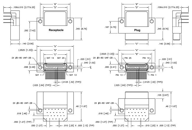
| Size | "A" | "B" | Plug "C" Receptacle | "D" | |||
| 9 | .375 [9.52] | .270 [6.86] | .160 [4.06] | .163 [4.14] | .175 [4.44] | ||
| 15 | .450 [11.43] | .345 [8.76] | .235 [5.97] | .238 [6.04] | .250 [6.35] | ||
| 21 | .525 [13.33] | .420 [10.67] | .310 [7.87] | .313 [7.95] | .325 [8.25] | ||
| 25 | .575 [14.60] | .470 [11.94] | .360 [9.14] | .363 [9.22] | .375 [9.52] | ||
| 31 | .650 [16.51] | .545 [13.84] | .435 [11.05] | .438 [11.12] | .450 [11.43] | ||
| 37 | .725 [18.41] | .620 [15.75] | .510 [12.95] | .513 [13.03] | .525 [13.33] | ||
| 51 | .900 [22.86] | .795 [20.19] | .685 [17.40] | .688 [17.47] | .700 [17.78] | ||
| 65 | 1.075 [27.30] | .970 [24.64] | .860 [21.84] | .863 [21.92] | .875 [22.22] | ||
|
Sales Drawings |
|||||||
|
CLICK on part number to download .stp file or .dxf file |
|||||||
*3D Models are standard Metal Shell profile. Please consult factory for other configurations
| Contact Resistance | 0.071 volt maximum drop @ 1.0 amps (.071 ohms) |
|---|---|
| Current Rating | 1.0 Amp Maximum per contact |
| Dielectric Withstanding Voltage | 250 V, RMS, 60 Hz |
| Insulation Resistance | 5,000 MΩ Minimum @ 100 VDC |
5 Ounce Maximum, 0.4 Ounce Minimum
#30–#32 AWG
| Vibration | Tested in accordance with EIA–364–28, Condition IV. No Damage or resistance change greater than 10 omhs lasting longer than 10 ns |
|---|---|
| Shock | Tested in accordance with EIA–364–27, Condition G. No Damage or resistence change greater than 10 ns |
| Durability | 200 connector mating cycles tested in accordance with EIA–364–09. No Damage or resistance change greater than 10ohms lasting longer than 10ns |
| Salt Spray | Mated connectors tested in accordance with EIA–364–26, Condition B. No exposure to base metal |
| Humidity | Mated connectors tested in accordance with EIA–364–31, Condition B (except steps 7a and 7b). Meet DWV and IR Requirements |
| Pin & Socket Contacts | Pins: BeCu alloy strip per ASTM–B–194 / Sockets: BeCu per ASTM–B–194 |
|---|---|
| Contacts Plating | Gold plate per ASTM B488, or SAE AMS 2422 |
| Metal Shells | Aluminum with electroless nickel or electrodeposited cadmium plating, Stainless Steel per ASTM A582, Titanium Alloy per MIL–T–81556, Unplated |
| Molded Insulators into Metal housing or Full plastic housing: | Insulating compound per MIL–I–16923. Liquid Crystal Polymer (LCP), per MIL–M–24519 GLCP–30F, 30% Glass |
| Hardware | Corrosion resistant steel per ASTM A 582/A582 or ASTM A 581/A581M, Passivated per SAE AMS–2700 |
 |
|||||||||||||||
|
|||||||||||||||