
![]() Preci-Dip Contact Technology Catalog (PDF document 1.5 MB)
Preci-Dip Contact Technology Catalog (PDF document 1.5 MB)
INTRODUCTION |
||||||||||||||||||||||||||||||||||||||||||||||||||||||||||||||||
| PRECI-DIP, a world wide leading manufacturer of precision machined contacts and related interconnect components is continuously improving its ability to design innovative contacts. This catalog provides general technical information on preci-dip contacts. It should help potential users make the best technical choice for a given application.
If no adequate solution can be found there, please contact us, as only a selected choice of all existing contacts is displayed. Furthermore, PRECI-DIP will be pleased to offer full support to design and manufacture customer specific contacts. |
||||||||||||||||||||||||||||||||||||||||||||||||||||||||||||||||
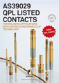
3 main groups of contact products are described and offered:
|
||||||||||||||||||||||||||||||||||||||||||||||||||||||||||||||||
PCB Connectors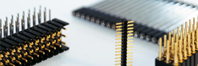 GENERAL SPECIFICATIONS The values listed below are general specs applying for preci-dip socket and pin connectors. Please see individual catalog page for additional and product specific technical data. Operating temperature range: -55 ... +125 °C
Spring-loaded Connectors & PAD Connectors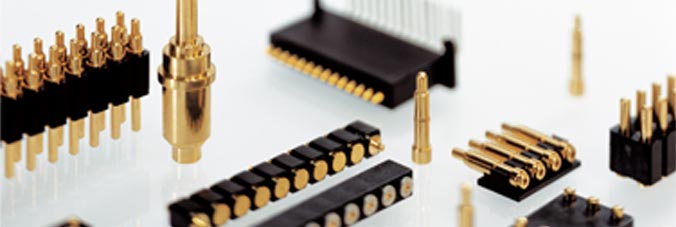 GENERAL SPECIFICATIONS The values listed below are general specs applying for preci-dip spring-loaded connectors. Please see individual catalog page for additional and product specific technical data. Operating temperature range: -55 ... +125 °C
Dil Sockets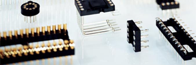 GENERAL SPECIFICATIONS The values listed below are general specs applying for preci-dip DIL sockets. Please see individual catalog page for additional and product specific technical data. OPERATING TEMPERATURE RANGE: -55 ... +125 °C
PGA / BGA / PLCC Sockets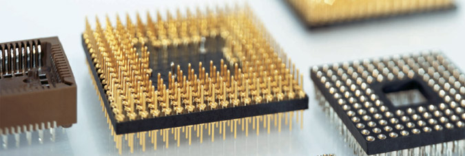 GENERAL SPECIFICATIONS
The values listed below are general specs applying for preci-dip PGA, BGA and PLCC sockets. Please see individual catalog page for additional and product specific technical data. Operating temperature range: -55 ... +125 °C
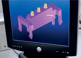
Custom Design
A competitive edge, the ability to innovate, and high productivity are some of the core values at PRECI-DIP. When it comes to Custom Design, there's an additional value: Teamwork. Time and again, turning customer ideas and imagination into reality is a very special challenge. This is one of PRECI-DIP's core strengths. Everything under one roof: the incomparable advantage of PRECI-DIP becomes even more obvious when it comes to Custom Design. Ready access to material resources is as critical as the expertise of our engineers and the art of developing and designing our own production equipment. Companies in all industrial sectors value their collaboration with PRECI-DIP for complete product and component solutions – today and tomorrow.
|
||||||||||||||||||||||||||||||||||||||||||||||||||||||||||||||||
 |
|||||||||||||||
|
|||||||||||||||